application. Reconstruction of the control part of the AC W200H boring and milling machine Liu Guoguang (Huangshi College, 435003) The original W200H boring and milling machine has good mechanical transmission performance, the armature carbon brush of the motor is seriously worn, and the spindle motor electric control system is separated by discrete components and small scale. The circuit is made up, the volume is large, the work is unstable, and the maintenance is complicated. To this end, it was decided to modify the control system of the equipment. 1 The overall transformation scheme feed motor power is 11kW, armature rated voltage 440V, rated current 28.5A, magnetic field rated voltage 190V, magnetic field rated current 1.6A, rotating speed is 3600r/min, Z-axis feed drag motor power is 6kW, armature rated voltage 440V, rated current 15A, magnetic field rated voltage 190V, magnetic field rated current 1. Speed ​​3000r/min Electrical control uses armature voltage regulation, DC irreversible system, acceleration and start when starting and braking The process of slowing down. 1.2 spindle drag electrical system requires the use of thyristor speed control, armature reversible logic loopless double closed loop control system, rated DC output voltage 440V, current > 410A, rated excitation voltage 220V, current 4.7A, according to machine tool transmission speed Range requires medium-sized horizontal boring machine D (main drive) = 25~60, (speed range D=ninax/nmin) and finishing machine S<0. Technical requirements for feed-and-drag electrical system, requiring thyristor adjustment Speed, armature reversible, rated DC output voltage 440V, current >30A, rated excitation voltage 190V, according to the machine drive speed regulation range requirements D (feed drive) = 30 ~ 150, (the speed range D is better, otherwise Creeping at low speeds). 1.3 The relay control part is safe and reliable for the logic of the relay. The line is simple and easy to maintain. The design of the whole electrical system must comply with the relevant national electrical standards. To this end, the Mitsubishi programmable controller FX2N*128MR was used to replace the huge relay logic circuit of the original machine tool. 2 spindle drag electrical system transformation spindle drive electrical system is the most important part of the trampoline electrical system, it is directly related to the machining performance of the machine tool, in the spindle drag electrical design, should use the armature reversible logic loopless double Closed loop speed control. The speed regulation range of the motor is divided into two areas, which are constant torque mode speed regulation under the rated magnetic field, and the weak magnetic speed increase mode is constant power speed regulation. In a reversible circuit composed of two sets of thyristors and anti-parallel, a circulating current may be generated under certain conditions. The so-called circulating current is the current flowing between the two sets of thyristors without passing through the load, which is divided into a DC circulating current and a pulsating circulating current. Circulation is unfavorable to the speed control system. Because of the circulation, the rectifier transformer and the thyristor capacity will increase. Originally, a balanced reactor with a limited circulation was added to reduce the circulation. Logical loopless flow is a kind of logic device to realize loopless flow. In the loopless speed control system, the reactor that restricts the circulating current is eliminated, thus saving cost. The double closed-loop speed control system has the advantages of fast dynamic response and strong anti-interference ability. Its static characteristics are typical excavator characteristics and are a basic form of automatic speed control system. The spindle dragging electrical system adopts the wide-speed DC spindle system ZSK?435A with high performance and domestic price. The system is DC reversible, the armature and magnetic field voltage are adjustable, the output current is 435A, the speed range is 1:100, and the static difference is ± 5%. The drag system of the Y, Z and Z axis feeds uses the DC wide speed servo SZKK? DC reversible, the output current is 50A, the speed range is 1:40ft, the static difference is ±4%. These two DC systems are The use of more integrated circuits makes the volume smaller, the power consumption is small, the anti-interference ability is strong, the maintenance is convenient, and the cost performance is high. From the main technical indicators, it can fully meet the transmission speed requirements of the boring and milling machine. When debugging the machine tool spindle, the parameters of the speed regulator and the current regulator should be adjusted according to the actual parameters of the machine tool to achieve the optimal start-up and braking transition process. At the same time, the limit current value and the field weakening point should be given. The values ​​are set to achieve the best drag effect. 3 Feeding and dragging electrical system transformation It is directly related to the machining performance of the machine tool. In the electric design of feed and drag, in addition to the armature reversible logic loopless double closed loop speed control, the W200H boring and milling machine X needs to be considered. The load of the shaft drag is nearly one hundred tons, the load of the Y-axis drag is nearly sixty tons, such a large load, and the drag motor is only 11kW. Due to the inertia, it must be gradually accelerated at the start, and gradually slow down when stopping. . Otherwise, when the motor is started, the motor will be blocked due to excessive torque required and cannot be started. When parking, the transition time is too long, reducing production efficiency. For this we use a given integrator circuit. The function of this circuit is to output a ramp voltage linearly related to time according to the output command of the logic circuit and the voltage reference value on the Rp potentiometer as the given voltage of the feed speed. The working principle is that the circuit of the given integrator consists of three operational amplifiers Ai, A2 and A3 and a RC network. Usl., Ui, U2, and Usc are the output of the input step signal, operational amplifiers Ai, A2, and A3, respectively, where the operational amplifier Ai is approximately open-loop, and its amplification factor is large, as long as US1 is greater than its limit value. The 1/100 output Ui will reach the limit value; the operational amplifier A2 constitutes the inverter, so that the whole integrator can form a negative feedback closed loop; the operational amplifier A3 and the capacitor form an integral link, which turns the US1. A signal for a certain slope. Their voltage waveforms are as follows. A negative sign indicates that the polarity of Usc is opposite to that of U2. It can be seen from the formula that in the tlt2 phase, when the machine feed and drag system is debugged, the X, Y, and Z axis drag systems are adjusted according to the actual parameters of the machine tool, except for the parameters of the speed regulator and the current regulator. In addition to adjustment, the main purpose is to adjust the integration time and limit current (generally set the limit current at start-up to 2.5 times the rated current) to achieve the best start-up, braking transition process and drag effect. 4W200H boring and milling machine PLC design PLC selection mainly considers the number of I/O ports required by the machine tool (in order to save the I/O port, if the machine part has entered the PLC, it will occupy more than a dozen I/O ports, and simplify The function of the circuit is not obvious, then it is not good to enter the PLC). Generally, the number of I/O ports of the selected PLC is more than the number of I/O ports required by the machine, because some I/O ports may be considered during machine design, and I/O ports may be added during machine tool debugging; After use, sometimes it is necessary to modify and add some functions, and I need to increase the I/O port. After many years of use, some I/O ports will be damaged. If there is a wealthy I/O port, you can change the port and program without changing the PLC. . According to the actual needs of the machine tool I / O port more than 50, so I / O port each has 64 Mitsubishi can be compiled 5 Conclusion This project has been successfully completed and has been put into use, the practice has proved that all electrical systems are stable and reliable , fully meet the processing performance of W200H boring and milling machine. Therefore, in the transformation of the machine tool should pay attention to: a. fully maintain and play the advantages of the original equipment; b. carefully analyze the control requirements of each part; C. try to use advanced and mature technology and well-known manufacturers of yuan, devices. Only in this way can it be ensured that the technical transformation funds are used reasonably, with short cycle and good reliability. (Finish)
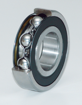
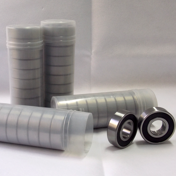
Rubber sealed deep groove ball bearings have rubber seals installed on one or both sides and are pre-lubricated with grease. These bearings often Also, snap rings are sometimes used on the outside edge. rubber sealed deep groove ball bearings with their simple design, high resistance and low-maintenance, while many different retainers are available, pressed steel cages are most commonly used.
The primary function of the seal is to protect the bearing from contaminants, it is important to keep the bearing clean when you take it out of the packaging so you don`t contaminate it just by handling it. Another function is, of course, is to make sure the bearing retains the lubricant. because of the rubber lip that`s making contact with the inner ring, we have the rubber rubbing on the inner ring of the bearing, increasing the friction in the bearing.
Our rubber sealed deep groove ball bearings use unique design polyamide and steel cage, The inner/outer rings and retainer(cage) are thicker compare with the Common bearings, stronger rivet, which consist more reliable structure. strong impact and heavy load with Grinding groove and super finishing technology. to offer the long life under extreme harsh environment.
Sealed type: With one seal (-RS) on one side or two seals (-2RS) on both sides. Sealed bearings are supplied with a contacting lip seal that excels in protecting the bearing from liquids and other foreign contaminants. The inherent design creates friction, drag, and in turn heat; factors that require consideration in high speed applications.
Rubber Sealed Deep Groove Ball Bearing Rubber Sealed Ball Bearing,Rubber Sealed Deep Groove Ball Bearing,Rubber Seals Deep Groove Ball Bearing Shandong Xinkaite Bearing Co., Ltd. , https://www.idlerbearing.nl

