Feiyiya Inclined Plate Clarifiers Use Gravity & Innovative Engineering
A gravity clarifier is the most economical method of removing solids from liquids, using natural gravity as the source of energy and it is free. A clarifier simply provides a non-turbulent zone where heavier than liquid solids, suspended by turbulence, are given sufficient time to settle to a quiescent surface. The HEI inclined plate clarifiers are compact units with multiple layers of settling area utilizing less than 25% of the floor space required by conventional clarifiers.
Principle of Clarifiers
A particle carried forward by the velocity of the liquid flow must settle at a rate that allows it to reach the bottom before passing through the clarifer. Thus, particles beginning at a point [a" must traverse some route lying between ab and ab` in order to avoid being carried over the outlet.
If V is the horizontal velocity of the liquid, S the solids particle vertical settling velocity, L the length of the settling device, and D its depth, then particles entering at point A will settle to the bottom of the device only if V does not exceed: S(L/D)Since Vmax / S = L / D then, Vmax = S (L / D)
Inclined plate clarifier, Lanmei inclined plate clarifier, Inclined Tube Settler,High-Efficiency Inclined Tube Wuxi Feiyiya Environmental Protection Technology Co., Ltd. , https://www.feiyya.com
Pneumatic rubber fender is the advanced anti-collision device for marine application in the world. It is made of synthetic nylon lines and compressed rubber sheet. With inner compressed air, it can float on the water and widely used as protecting medium. It is usually used as an important protecting medium to prevent a collision in craft works and mooring works.
 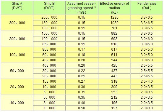
Advantage and application:
Compared with traditional bumper-style rubber fender, it has the following features, absorbing greater impact, less reverse impact on the ships, easy installation, more elasticity, not being bent out of shape under pressure, less weigh and practical and economical. So pneumatic fender has widespread application on oil tankers, container vessels, luxury yachts, ocean platforms, larges shipyards, military ports and larger underwater foundations of bridges, etc.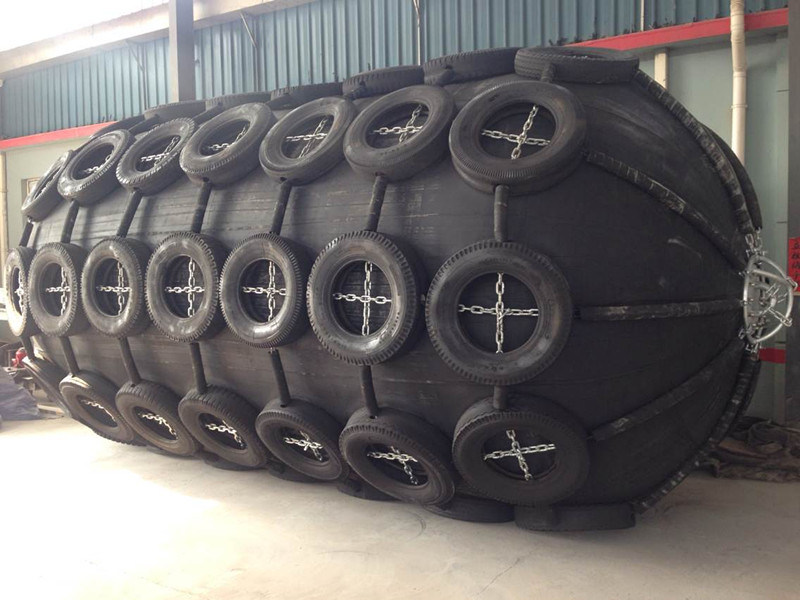
Purpose
1. Installed in the terminal and dock, used the ship shore and landing.
2. Installed in the ship board, used the ship close to ship.
3. Can as float rod on the sea.
4. Can used carry goods on the sea
5. Used airproof pipe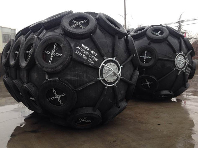
Specifications:
1. Small-scale Diameter: Less than 1meter; Length: Less than 1.5meter
2. Medium Diameter: More than 1meter, Less than2meter; Length: More than 1.5meter, Less than 4 meter.
3. Large-scale Diameter: More than 2.5 meter; Length: Length basis customers' requirement
Since we own a professional technicians team, so the most advantage is that we can suggest you the most suitable quantity of airbags needed according to the actual condition of the ships and structures, which can avoid wasting the labor, cost and time. Our mission is provide world class goods to customer, so we guarantees high standards and performances of all products. Customer requirements are strictly followed during all production phases.
Storage of pneumatic rubber fender
1. When not using for a long time wash the fender surface, dry up and fill in sufficient right of compressed air to lay in a cool dry and well-ventilated place
2. The storage place of pneumatic rubber fender should be far away form heat source
3. Try to keep fender away from acid alkali grease and organic solvents.
This marine ship fender catalog
D*L
Initial pressure(Po) is 0.05Mpa
Test pressure
Initial pressure(Po) is 0.08Mpa
Test pressure
Mpa
Mpa
Weigh
R(KN)
E(KJ)
Weigh
R(KN)
E(KJ)
0.5*1.0
24
64
6
0.15
27
86
8
0.18
0.6*1.2
35
86
10
0.15
39
124
16
0.18
0.7*1.5
50
136
17
0.15
55
180
24
0.18
1.0*1.5
80
181
32
0.15
88
238
45
0.18
1.0*2.0
100
256
45
0.15
110
338
63
0.18
1.2*2.0
120
296
62
0.15
120
389
88
0.18
1.35*2.5
170
426
100
0.15
183
560
141
0.18
1.5*3.0
320
578
152
0.15
355
760
214
0.18
1.7*3.0
400
637
190
0.15
440
840
268
0.18
2.0*3.5
590
875
306
0.15
650
1150
430
0.18
2.5*4.0
1050
1378
660
0.15
1150
1815
925
0.2
2.5*5.5
1350
2010
932
0.118
1480
2650
1315
0.2
3.0*5.0
1880
2100
1070
0.18
2060
2520
1360
0.25
3.0*6.0
2180
2530
1360
0.18
2400
3210
1670
0.25
3.3*4.5
2020
1880
1170
0.18
2220
2470
1640
0.25
3.3*6.5
2700
3010
1810
0.18
2960
3960
2530
0.25
Note: The weight of the ball by ball weight (without jacket), the weight of error of ± 10%; reaction force error of ± 10%Â
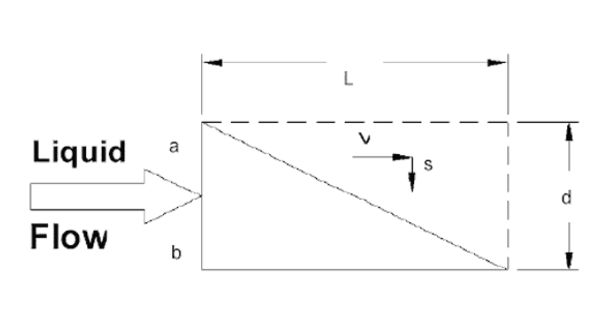
Therefore, the velocity at which a horizontal clarifying device may be operated successfully is directly proportional to its length and inversely proportional to its depth.
This analysis applies to multiple horizontal plate units also. The spacing between plates is usually a few inches as opposed to a depth of several feet in a horizontal tank; therefore, [settling-out" times are dramatically reduced. The flow must be non-turbulent to prevent settled solids from being re-entrained within the moving liquid. Small plate spacing and a large surface area permits laminar flow at higher velocities than large horizontal tanks would allow.
Horizontal clarifying devices become self-flushing if they are inclined at an angle which exceeds the angle of repose of the settled solids. In such cases, flow enters the lower end of the device where settling particles move to the floor eventually sliding back out the entrance. Clear effluent leaves the top of the device.
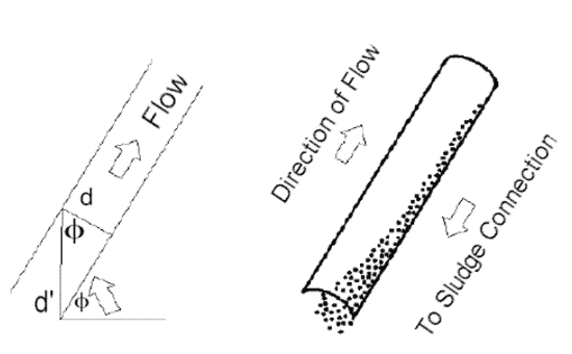 However, when the device is inclined, the furthest settling particles no longer fall through distance D but some longer distance D`. This new longer settling distance D` is related to D by the relation: D = D` cos Ø.
Theta [Ø" is the angle, the device is inclined to the horizontal plane. Thus settling distance is increased by the factor: 1/cos Ø In the case where Ø = 60º, 1/cos Ø = 2.
The maximum settling distance is twice the distance between the plates. It is apparent then that the lower the angle of inclination, the smaller the settling distance. However, the angle of inclination must exceed the angle of repose of the solids to be separated. The previous equation may be modified to express the cosine of an inclined plate clarifying system as:
Vmax = L / (D / cosØ) (s) = L·cosØ / D (s)
Inclined Plate Clarifiers
A reduction of the required floor space is acquired by diminishing the separation between the horizontal plates to a few inches and stacking the settling surfaces. Inclining the plates to provide self flushing, 45º for heavy particles and 60º for light particles, reduces the available horizontal projected area (effective settling area) by a factor equivalent to the cosine of the angle. The surface area diagram (below) graphically compares the floor space requirements of an HEI inclined plate clarifier with the equivalent horizontal projected settling area.
Settling Rate
The settling rate for a specific solids should be determined by standard laboratory tests. Light particles, such as metal hydroxides, usually require a design parameter of 0.25 – 0.50 gallons per minute per square foot of horizontal projected area. These low density solids require the inclined plates to be set at a 60º angle to induce the particles to slide down the plate. Heavier particles (such as sand that easily flow) will readily slide from plates set at a 45º angle.
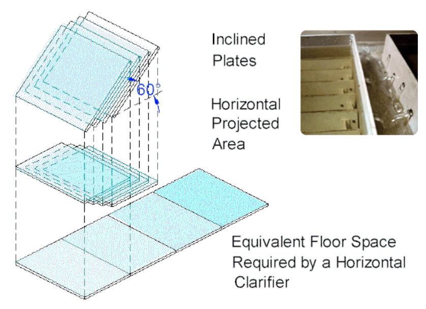
Maximum flow rate of an inclined plate clarifier is based on the flow rate per unit of a horizontally projected surface area. Retention time in the clarifier is not a design criteria. However, attaining optimum performance requires the prudent design to recognize several additional, very important factors.